The FilaBilly Dehumidifier
by kbob
This is Part 2 of several. Start at the beginning.
The dehumidifier is the heart of the FilaBilly Humidor. It uses a Peltier thermoelectric cooling device to chill incoming air. That causes water vapor to condense out onto an aluminum heatsink. From there, the water drips down through a tube into a container of some sort. The hot side of the Peltier is attached to a CPU cooler. The CPU cooler’s fan moves air through both the hot and cold sides.

The dehumidifier is published to Printables. Go there if you want to make your own.
Mechanical Design
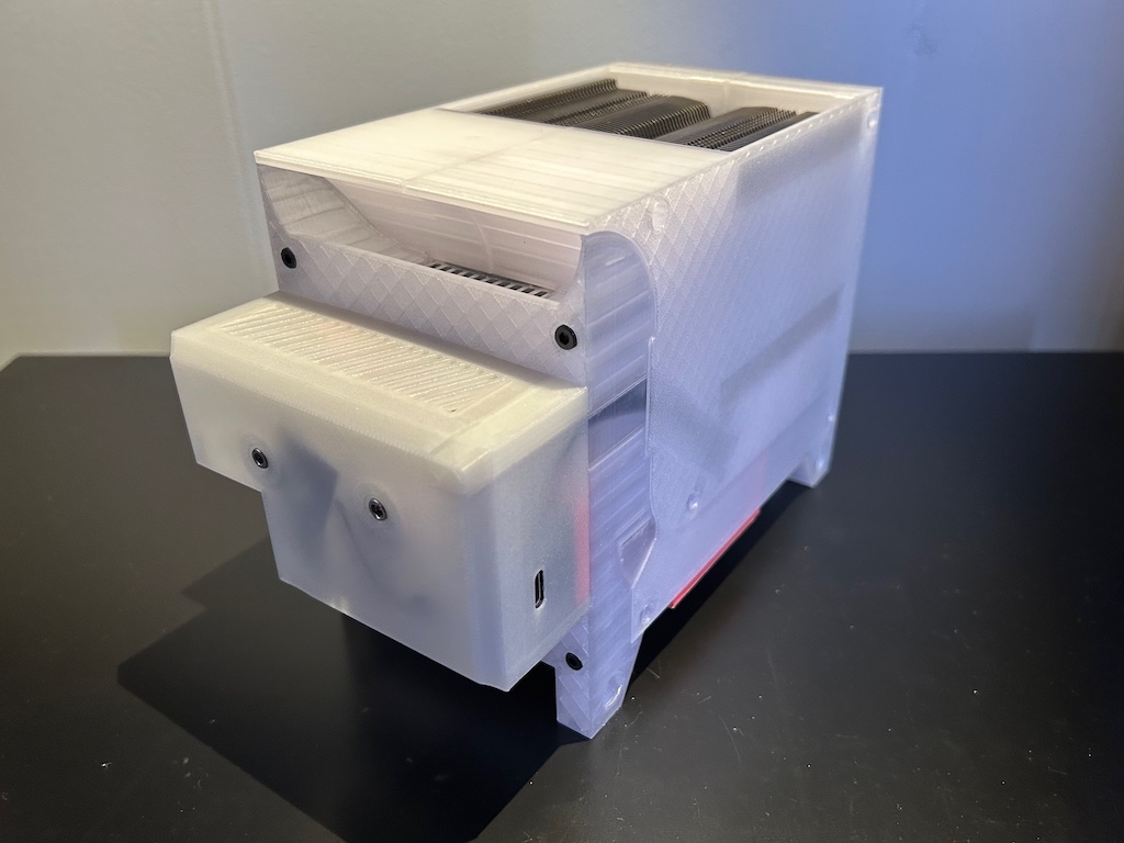
Mine is a near clone of Ben Krejci’s filament dehumidifier. The biggest difference is that mine uses a PC CPU cooler that you can buy today (April, 2025). Other differences are that mine moves the electronics from the side to the front to keep the package slim, has an adjustable vent size, and has numerous detail changes.
One of my concerns is that the FilaBilly Humidor won’t hold all my filament. So I’ve worked on keeping the dehumidifier slim. To that end, I moved the electronics box from the side to the front, and I moved the fresh air intakes from the sides to the bottom.
Making the box fit the Noctua NH-U9S was tedious but straightforward. I printed six prototypes before I got one that fit, but now it’s snug and glove-like.

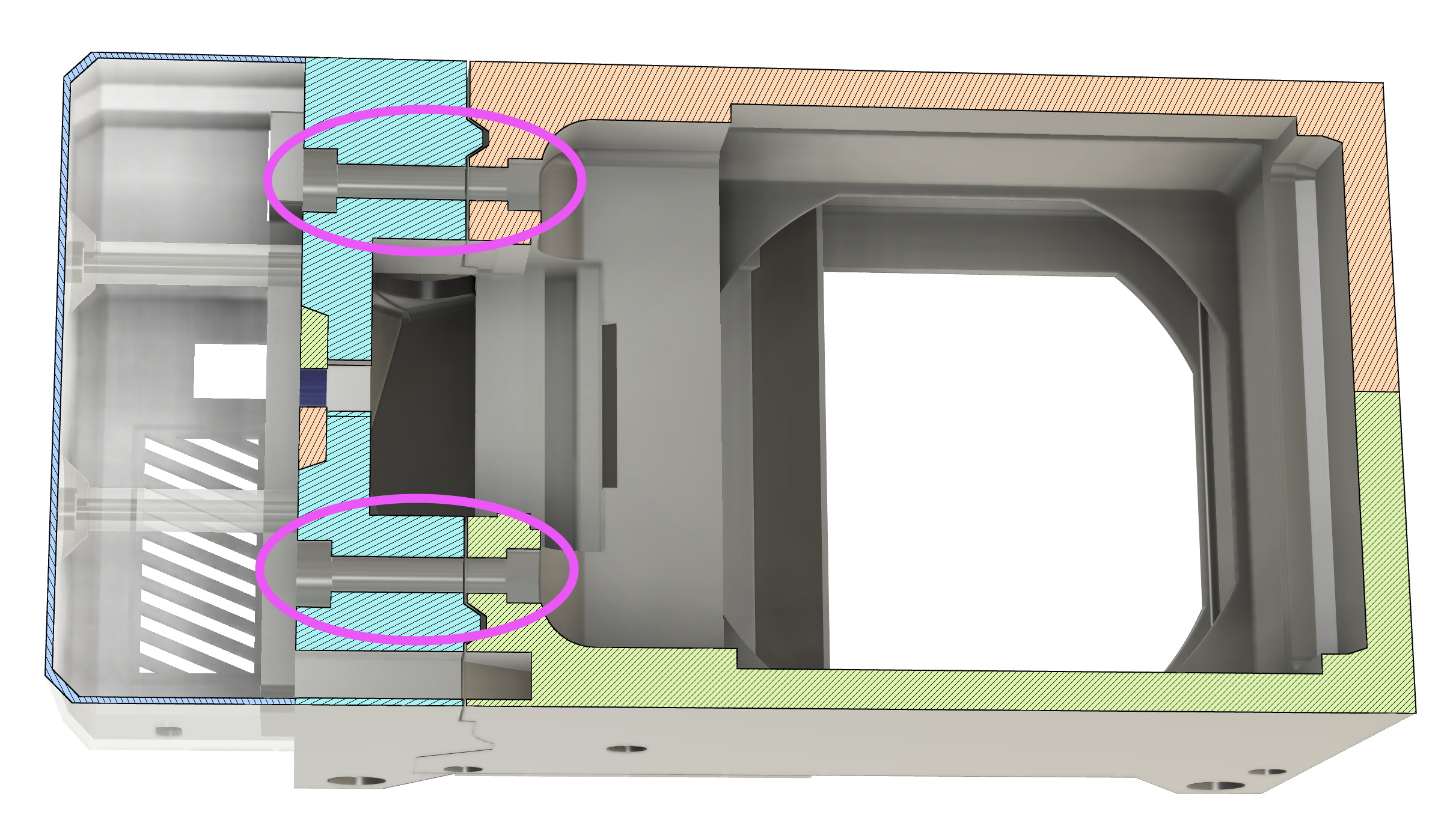
Like Ben’s, I use compression screws to press the cold side heatsink, the Peltier, and the CPU cooler together. I significantly upgraded them to M5 screws with nuts.

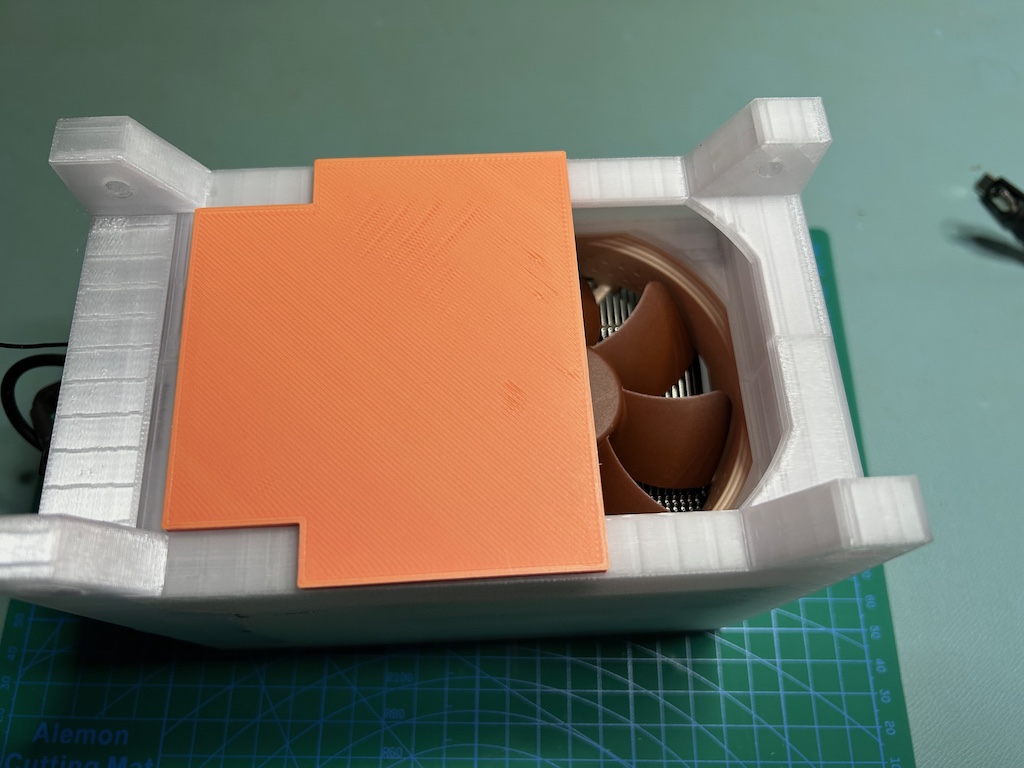
The hot side needs more airflow than the cold side. So the hot side uses both the chilled air and fresh air to cool. Since I don’t know the optimal ratio of the two, I made the fresh air vent adjustable. It just slides open and closed.
In that photo, you can also see that there are screw holes in the feet. I plan to attach some kind of bracket that clips the dehumidifier onto the FilaBilly rails. It will screw onto the feet.
Electronics
Since I very much want to publish this design and encourage others to make it, I took the trouble to draw up a printed circuit board for the electronics. It’s a simple two layer board, mostly connectors, all through-hole. It has connectors for an ESP32 board and all the off-board peripherals, and it has a big power MOSFET to drive the Peltier. It has a single 12 volt supply, and it uses a regulator on a power board to derive 5 volts for the ESP board. Again, the eletronics are mostly Ben’s, but I did add tach monitoring for a PWM fan.
ESPHome

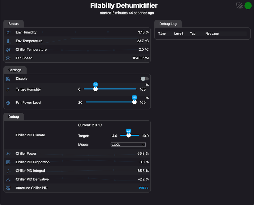
And then there’s ESPHome. ESPHome is kind of amazing. I wrote/cribbed 300 lines of configuration file (in YAML!), and ESPHome turned that into embedded firmware with Wi-Fi, mDNS, a web server, over-the-air updates, Home Assistant integration, reporting for 4 sensors and 4 virtual sensors, 3 virtual control inputs, PWM fan control, and a PID thermostat for the chiller with freeze/defrost cycles.
On the other hand, ESPHome is kind of annoying. Bringing in powerful modules is easy, but getting them to interact with each other is hard. YAML Ain’t Markup Language, but YAML ain’t a programming language either. Except ESPHome pretends it is. Doesn’t this look like code?
script:
- id: maybe_start_script
    then:
    if:
        condition:
        and:
            - switch.is_off: disable_switch
            - binary_sensor.is_on: high_hum_binary_sensor
        then:
        script.execute: start_script
There are ways to escape to C++ in ESPHome, but they’re limited.
Anyway. ESPHome. Love/hate.
The Assembly Guide
The dehumidifier is complicated enough that it needs more than a few notes about how to put it together. So I wrote an Assembly Guide. Currently at 35 pages, it lists the parts needed, lists the ways the various parts need to be prepped, talks about assembling the PCB, and shows step-by-step photos of how the pieces go together.
I used Apple’s Pages.app to lay out the assembly guide. I did my best to create something that’s both good looking and useful; I probably failed on both counts.
Learning
If there’s a theme to this project, it’s about using tools that either I don’t know or have forgotten how to use. KiCad, ESPHome, Apple Pages, even this ‘blog’s software, Jekyll with extra scripting. So I’m pretty happy to be broadening my skill set — I just hope I get to use these tools again before I forget them.


