Deep Synth: Audio Rework
by kbob
This is Part 2 of several. Start at the beginning.
The Deep Synth project grew out of the 1Bitsy-1UP project. So let me tell you about the 1UP and its audio section.
The 1Bitsy is based on an STM32F415 chip, which has three I²S peripherals. Unfortunately, due to pin conflicts, the 1UP can’t use those.
Instead, the 1UP uses the STM32’s two channel DAC for stereo audio output. The DAC has 12 bit resolution. Since the 1UP is an homage to the Game Boy, we thought 12 bit was probably good enough for bleeps and boops.
So I wrote an audio driver and a test application.
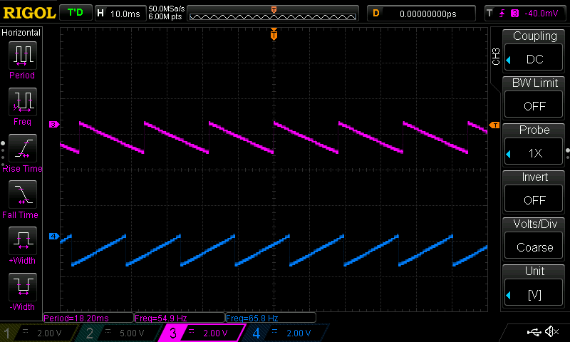
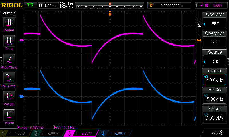
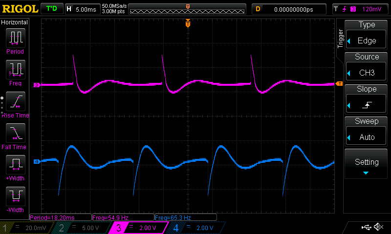
When I looked at the audio on an oscilloscope, though, it didn’t look good. Here’s a square wave. The left channel is above the right.
And here are two sawteeth. 55Hz on the left, 65Hz with opposite polarity on the right.
So we looked at the circuit. (We means @esden, J—, and @scanlime.) There were a couple of problems. The DACs fed an RC high pass filter, and from there went into a digital potentiometer (Microchip MCP4661). The digipot wiper fed a headphone amp (TI TPA6135A2). We identified a couple of issues.
- The RC time constant was too high.
- The digipot’s power rails were 0V and +3.3V. The audio signal was dipping below 0V, sending the pot into uncharted territory.
- The digipot has linear taper, and audio attenuation should use a log taper.
So we reworked the board to move the high pass filter downstream of the digipot. And then the headphone jacks started breaking off.
- SMT headphone jacks are too fragile.
And then we started talking about redesigning the whole audio section. Here is a summary I wrote at the time.
So I started designing the new audio output section using the PAM8019 from Diodes Incorporated. It would have a through hole headphone jack and a volume potentiometer. I made a new board that would attach to the 1UP in some unspecified way.
My first thought was to sandwich the audio board between the 1Bitsy and the 1UP. I got this far in the design.
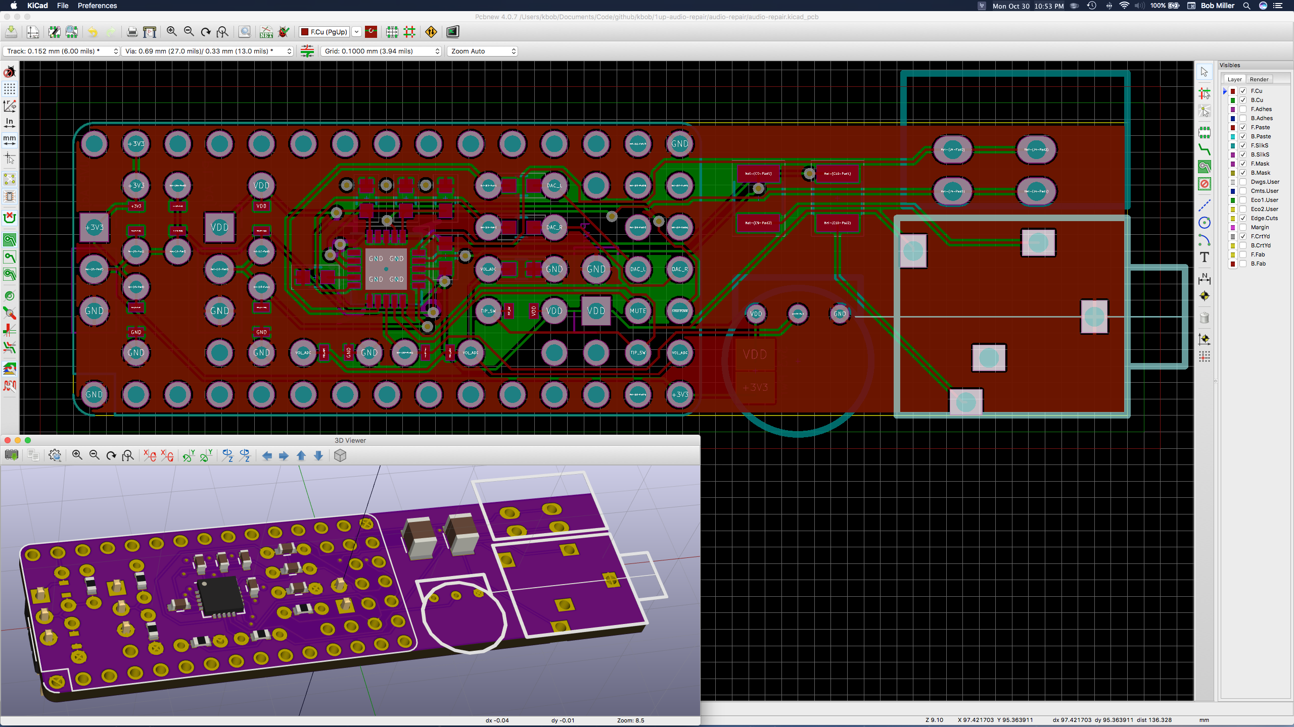
That was not the answer. The routing was a mess. I used SMT passives, but paired each with a set of through holes to replace the passive if testing showed it was the wrong value. (I am not (yet) very good at soldering SMT, and I’m not keen on SMT rework at all. And the PAM8019 datasheet had left me with several questions about component values.) And how could you replace components if the audio board was under the 1Bitsy?
So I backed up and designed a board that would not fit the 1UP but would let me test components. Here is the second board, V0.2, after it was debugged.
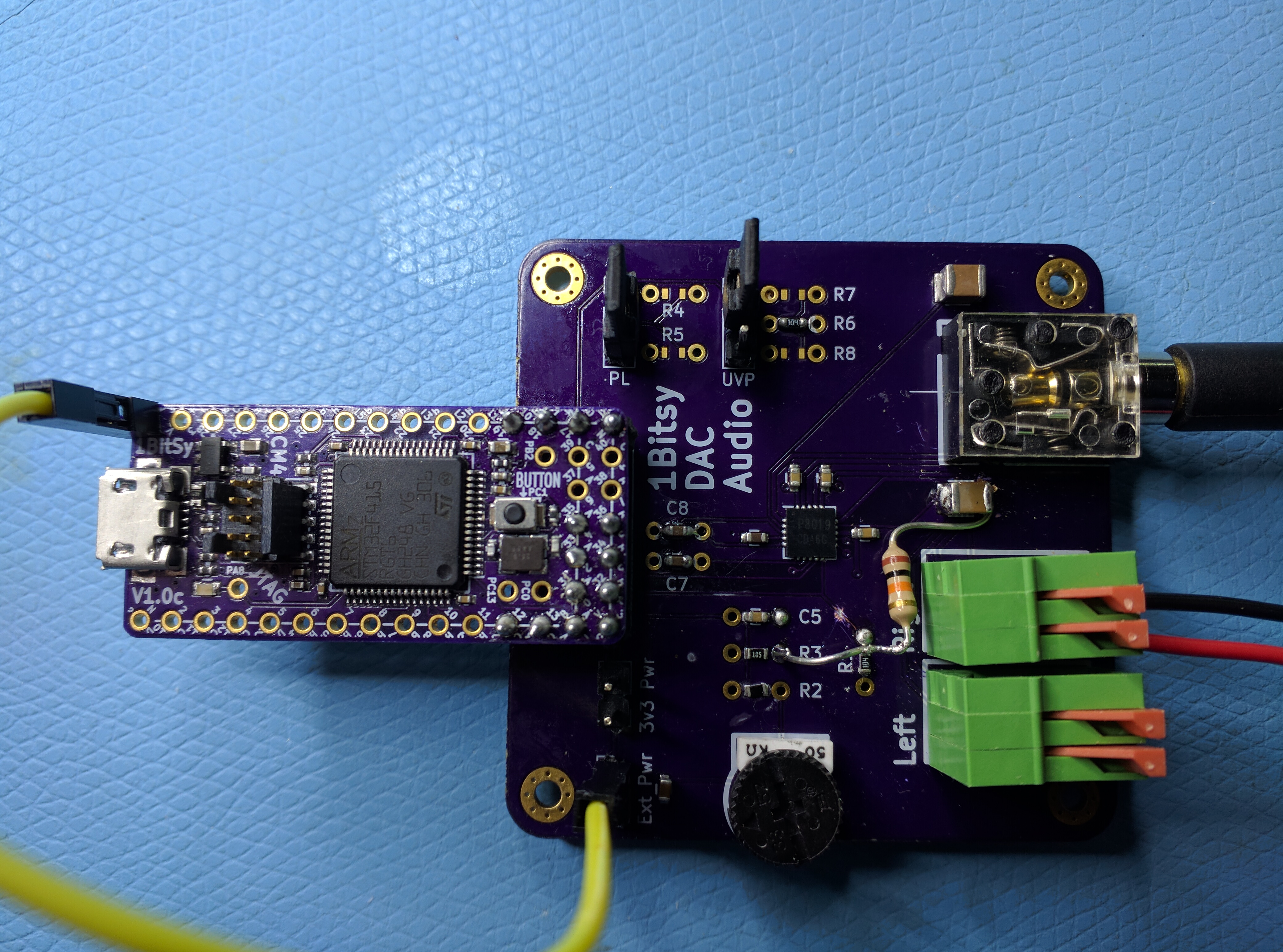
The jumpers in the lower left allow switching between regulated 3.3V and battery power. The two jumper blocks at the top allow bypassing voltage dividers, shorting a pin directly to +V or GND.
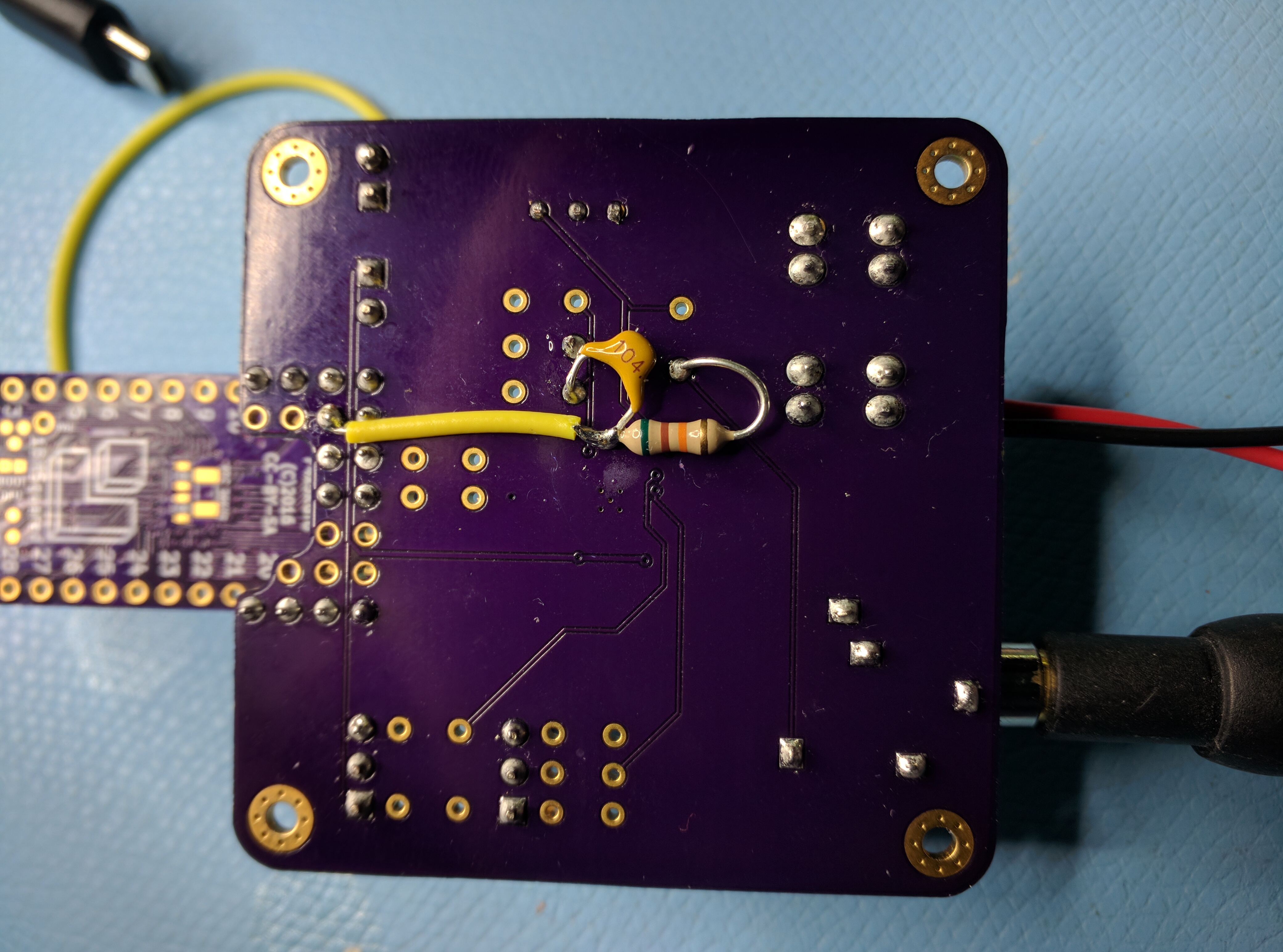
The rework corrects a bug in the headphone sense circuit.
There are two speaker jacks – we only want mono, but stereo is available on this revision.
Then I spent an afternoon measuring different values for the voltage dividers. One of them was replaced by a jumper to ground, and the under voltage protection got values that shut off the amplifier power just before the STM32 shut down.
So it was time for a new board. Here is board number 3. It solders onto the top of the 1Bitsy. I made three of them, and they all worked.
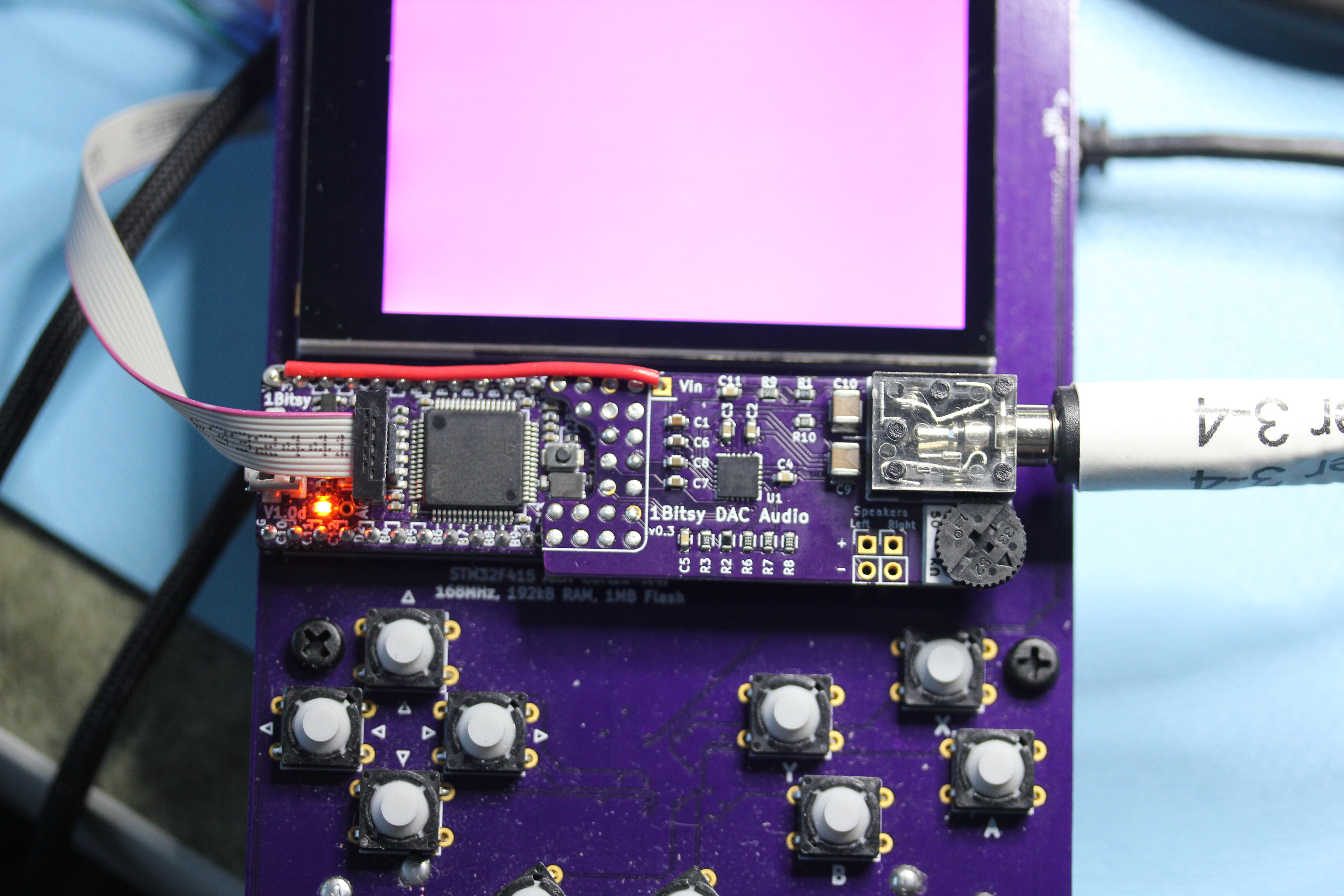
And that is how the 1UP got its groove back.